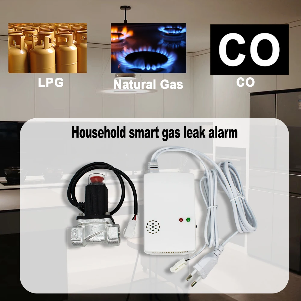
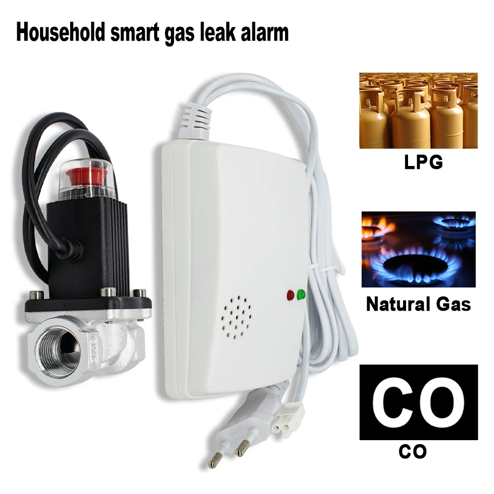
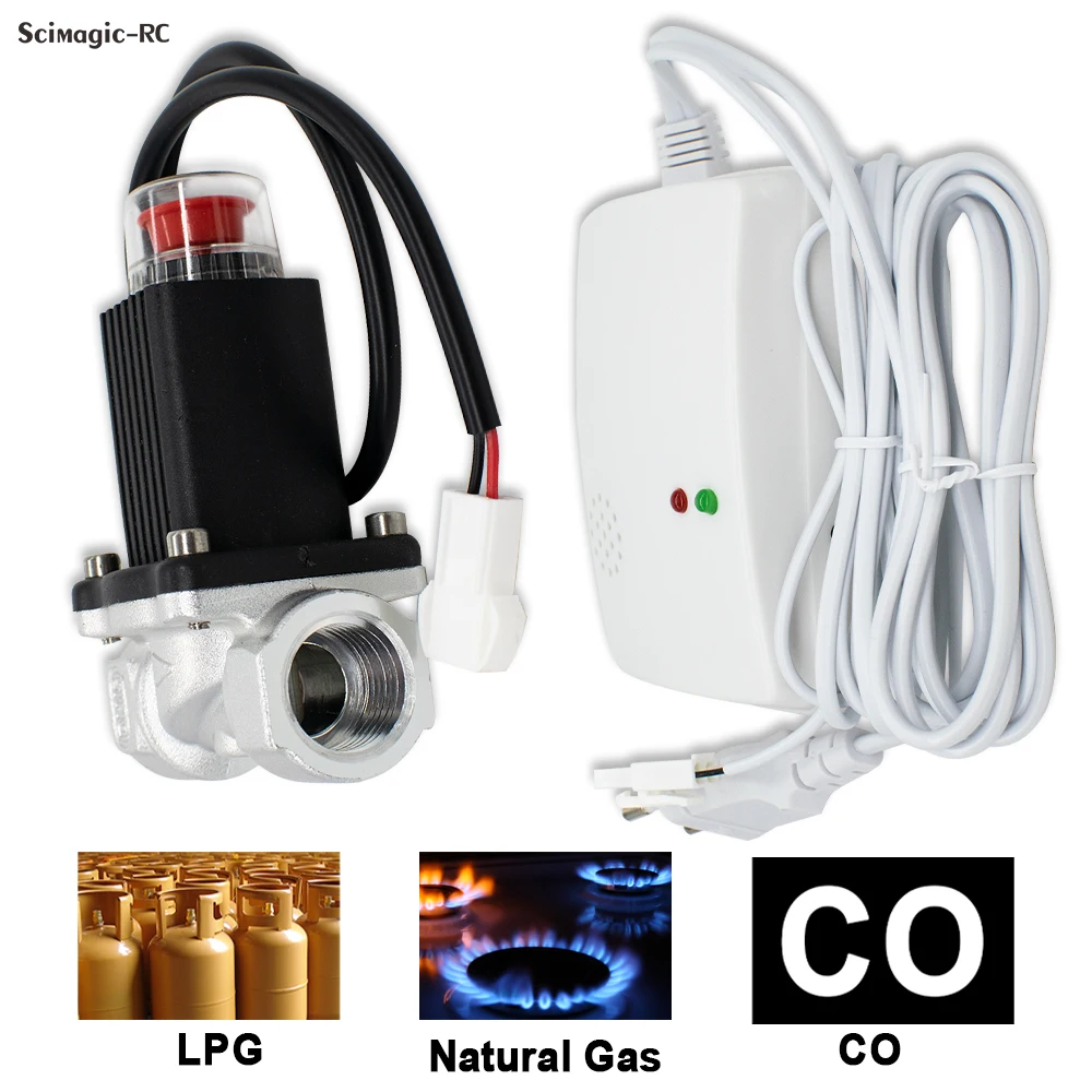
Scope of use
To natural gas, city gas, liquefied petroleum gas, etc The excessive concentration of combustible gas makes a reliable alarm, which can be widely used Used in homes, gas stations, coal mines and other occasions.
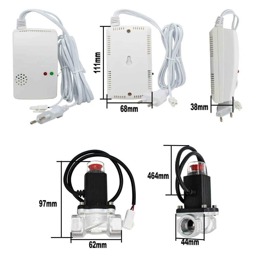
Detector Technical Parameters
Characteristics:1.1
1. Wall-mounted: mounted on the wall
Ceiling type: installed under the ceiling of the ceiling
2.Power supply: AC220V or DC12V
3.Static power consumption: <1.3W.
4.Alam power consumption:<1.7W
5.Operating environment: Temperature: -10°C-45C
The temperature: 30-90%
6.Alarm concentration
Natural gas: 10-~25%LEL
LPG:10-25%LEL
City gas: 2-5%LEL
7.Alarm output sound and light alarm, normally open or normally closed Signal, control exhaust fan, solenoid valve, machinery Hand signal (optional)
Gas Emergency Shut Off Solenoid Valves User's Manual
●Introduction:
The valve is a series of gas emergency shut off solenoid valves, specially designed as gas pipe breaker for emergency use . It can be connected with gas leaking detection sensor , fire alarm circuit or other intelligent sensor modules so that on site or remote shut down on gas supply (manually or automatically) is possible, hence ensuring the safety on gas usage the valve features an auto-close when strong vibration is detected .After close, manual operation is required to turn on the valve. This feature meets safety regulations in the event of an accident.
●Technical Data
♦Suitable gas types: natural gas
♦Closing modes: current impulse non - corrosive gas etc or manual
♦Driving Voltage: DC9-12V
♦Sealing material: NBR rubber
♦Driving current :<1.5A (impulse)
♦Pressure max:50kpa
♦Close time :<1 sec
♦Connection: Gl/2, G3/4”,Gl"
♦Lead wire :0.4m
♦Turn on manual Working Principal
When the switch is pressed, the capacitor discharges and provides an electric current so that a coil can generate strong magnetic held to pull down the valve, achieving the closing within one second. +9~2V
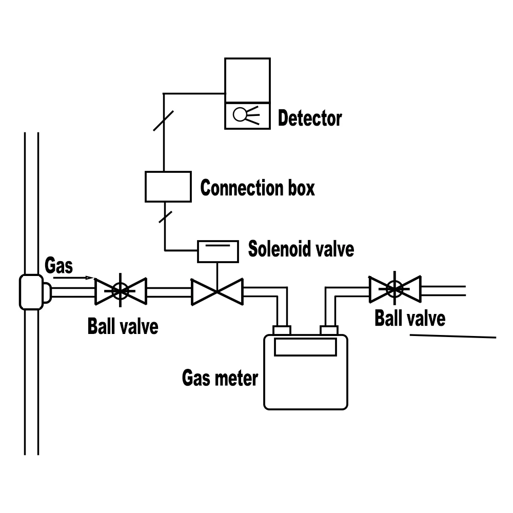
Installation Requirements
1. Only request contractor can install this valve.
2. The valve must be installed after the indoor main valve.
3. A valve should be installed in the gas flow direction marked on the valve body, The coil must not be placed in downward position A valve may be installed horizontally or vertically.
4. the valve control wires should be connected correctly.
Brown indicates positive while Blue stands for negative.
Mismatch lends to fatal consequences.
5.During pipe maintenance, such as pressurized pipe cleaning . the valve should removed to avoid damages to the valve sealing.
6.During pressure tests, the valve should be turned on.
7.The valve's opening knob can be pulled up when equal pressure have been reached at the inler and the outlet of the valve,
8. Wrong polarity, wrong voltage or prolonged power on may damage the electromagnetic coil,
9. Our guarantee does not include any damage to the valve or loss of parts due to keeping or actionsin violative regulations.
●Wiring Requirements
1.Cable:dual core, 3 X 0, 75mm2 Or above
2, Length of cable < 50meters
●Maintenance
Inspection must be done regularly, open and close it , In case of failure, notify the contractor immediately for repair.
Detector Installation Guide
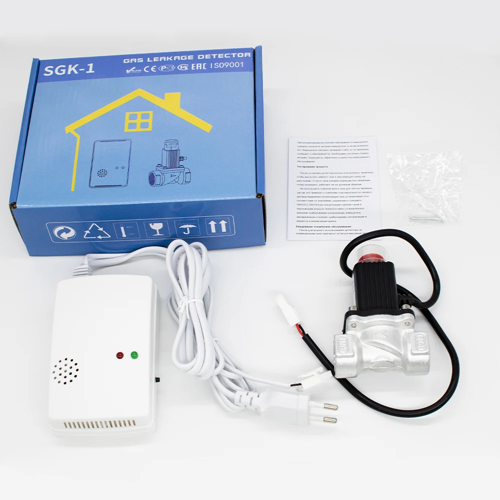
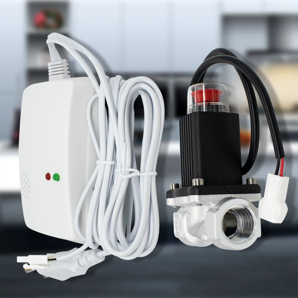
2.1: Verify the list of parts
A complete set of alarms includes: One alarm host An instruction manual
One external terminal line (networking or tandem models)
2.2: Install gas leak alarm according to the proportion of gas
Natural gas, city gas: because it is lighter than air, will suspend On the ceiling, so the alarm should be installed 0.3- below the ceiling 1.2 m, suitable place within 1.5 m radius of air source. Installation attention: gas leak alarm
1.Do not directly face the lampblack and steam of the stove;
2. Do not install in a well-ventilated place:
3.Do not be blocked by curtains or cabinets;
4. Do not install in the bathroom and other places where the steam is large.
2.3: Instructions for the use of external terminal Cables
1.When the 12V system power supply is used, the red line of the external terminal is correctly connected The pole and the black wire are connected to the negative pole
2.Networking start signal output: White line: normally open contact. Green line: normally closed contact. Yellow line: common end.
3. Connect the white wire and yellow wire in series to the exhaust fan On the lighted line of fire;
4.No linear type: according to the requirements of alarm host, work frequency Rate 315M or 433M is optional and programmed on the transmitter module Good data code and address code.
Usage Guide
3.1: preheating state
I top suction type: connect AC220V or DC12V civil source, this
When the green indicator light flashes, it indicates that the alarm is in preheat state
Il Wall-mounted: connect AC220V or DC12V power supply, this
When the red indicator light is on, it indicates that the alarm is in a good position Surface thermal state.
3.2: Monitoring status
I. Top suction type: after about 3 minutes, the green indicator light will be on The alarm is in monitoring state.
II. Wall mounted: about 3 minutes later, the red indicator light comes, green The color indicator light is steady on, indicating that the alarm is in the monitoring state.
3.3: Alarm state
When the concentration of gas in the environment reaches the alarm concentration, red The color lights are flashing, the buzzers are whistling, Output switch signal at the same time.
3.4; Restores the status
When the concentration of gas in the environment drops below the nominal concentration, the red indicator light goes off, the buzzer stops ringing, Switch signal restores to original status.


 Aestus max. 30ºC.
 Mauris maximus 110ºC.
 Ne frangas.
 Nec in bin.
 Condite in frigidis.